 This simple calibration procedure does not use a Bessel null to
indicate the modulation index and the exact frequency of the test tone
is not critical. The peak-to-peak deviation is read directly off a
spectrum analyzer.
This simple calibration procedure does not use a Bessel null to
indicate the modulation index and the exact frequency of the test tone
is not critical. The peak-to-peak deviation is read directly off a
spectrum analyzer.
This simple calibration procedure does not use a Bessel null to
indicate the modulation index and the exact frequency of the test tone
is not critical. The peak-to-peak deviation is read directly off a
spectrum analyzer.
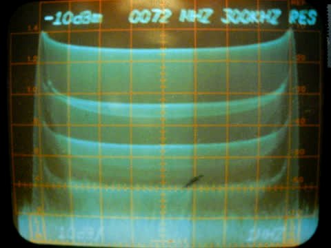
At high modulation indexes, the bandwith of the modulation envelope equals the peak-to-peak deviation of the modulating signal. Note that the bandwith of the modulation envelope is measured down -40 db from maximum.
A test tone of proper amplitude in the higher audio frequency range is applied directly to the frequency modulated oscillator of the FM TV transmitter. A sample of the FM TV transmitter RF output is applied to the spectrum analyzer. Alternatively, a RF sample from a FM TV receiver intermediate frequency can be used to feed the spectrum analyzer.
The photo at right shows the modulation envelope taken off the IF of a receiver. The modulating test tone into the transmitter was 9.9 khz. The -40 db points on the modulation envelope indicate a peak-to-peak deviation of approximately 8.35 Mhz or a peak deviation of approximately 4.17 Mhz. In this case, the modulation index is approximately 421.
You CAN apply the test tone to the input of the pre-emphasis network but it will need to be higher in amplitude by a factor of approximately 4.43 above that required at the FMO due to attenuation in the pre-emphasis network. Approximately 4.43 volts peak-to-peak will be needed for a FMO input of one volt peak-to-peak. Do not do this if there are any active networks before the pre-emphasis network as they may be overloaded resulting in a distorted test tone at the FMO input and erroneous results!
 The intermediate frequency filter bandwidth of the FM TV receiver
determines the maximum peak deviation which can be used. If you
deviate beyond the pancake flat portion of any RF filter,
intermodulation will result. Bell Telephone Systems designed for
North American standards FM TV microwave radios used IF filters of -3
db at 22 Mhz in order to obtain a pancake flat bandpass of 16 Mhz
through the IF center frequency. This is the passband required for a
peak deviation of 4.0 Mhz which includes video plus subcarriers AND NO
intermodulation! Video deviation is 3.2 Mhz peak with 200 Khz peak
for each of four subcarriers. The passband for European Standards
(CCIR) is -3 db at 30 Mhz to achieve a pancake flat response of 25 Mhz
to carry a peak deviation of 5.6 Mhz with NO subcarriers. See my ATVQ
article 'Comments on Commercial FM TV Standards' accessible from the
home page for more information.
The intermediate frequency filter bandwidth of the FM TV receiver
determines the maximum peak deviation which can be used. If you
deviate beyond the pancake flat portion of any RF filter,
intermodulation will result. Bell Telephone Systems designed for
North American standards FM TV microwave radios used IF filters of -3
db at 22 Mhz in order to obtain a pancake flat bandpass of 16 Mhz
through the IF center frequency. This is the passband required for a
peak deviation of 4.0 Mhz which includes video plus subcarriers AND NO
intermodulation! Video deviation is 3.2 Mhz peak with 200 Khz peak
for each of four subcarriers. The passband for European Standards
(CCIR) is -3 db at 30 Mhz to achieve a pancake flat response of 25 Mhz
to carry a peak deviation of 5.6 Mhz with NO subcarriers. See my ATVQ
article 'Comments on Commercial FM TV Standards' accessible from the
home page for more information.
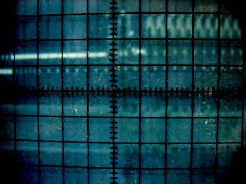
The picture at right shows oscilloscope displays of video above and subcarrier below with high levels of video amplitude modulation on the subcarrier. This mixing of modulation information is intermodulation. The demodulated audio from a subcarrier like this one is usually very noisy at white level or with character generator running, and sinc noise is plainly heard. It also affects the video but due to the high frequency of the subcarrier impressed upon the video, one can not see it on the oscilloscope. It can be seen in the received picture as a fine grain which changes with average picture level.
You can look at your own signal by filtering out a subcarrier from received baseband and using the video to sinc the oscilloscope. If you are trying to get '4 Mhz peak' or more probably '5.6 Mhz peak' through a bandpass of -3db at 12 Mhz (more or less), you are sure to see and hear lots of the above! The solution is to simply turn down the deviation of the FM TV transmitter. Once you are deviating within the linear limits of the RF filters, your audio subcarrier amplitude can be very low compared to the video, and still have clean demodulated audio.
This picture came from the demodulated baseband of a commercial microwave FM TV receiver designed for North American Standards after the broadcast engineer used European Standards for deviation calibration. This was not uncommon due to the lack of understanding the basic principals of analog FM TV.
.
I retired from commercial television broadcast engineering approximately seven years ago. I had approximately thirty years experience with FM TV in the form of hundreds of miles of microwave FM TV transceivers used in studio-to-transmitter and transmitter-to-studio relay links for Duhamel Broadcasting Enterprises in Rapid City, South Dakota. I was chief engineer for KSGW - TV in Sheridan, Wyoming for most of that time.