Comments on Commercial FM TV Standards
as Applied to Amateur Operations
by J. R. Mathison, WB9OQM
The following is the draft of my original article which
was published in Amateur Television Quarterly (ATVQ) -
Winter 1994.
Please see a later edition of the ARRL Handbook for basic
information and definitions concerning video, pre-emphasis, and
FM TV transmission systems.
CCIR Recommendation 276-2 "Frequency Deviation and the Sense of
Modulation for Analog Radio-Relay Systems for Television"
paragraph 1. recommends "that the value of frequency deviation
without pre-emphasis in radio-relay systems for television should
be 8.0 Mhz peak-to-peak referring to the nominal peak-to-peak
amplitude of the video-frequency signal (see Recommendation 567).
Recommendation 567 is the specifications for video and defines
the "video- frequency" signal as excluding synchronizing pulses.
If the video-frequency signal deviates the FM carrier 8 Mhz
peak-to-peak, then the composite video (including sync) will
deviate the FM carrier 140/100 IRE x 8 Mhz equals 11.2 Mhz p-p or
5.6 Mhz peak deviation. It is assumed that deviation is directly
proportional to amplitude at the input of the frequency
modulator.
CCIR Recommendation 276-2 in paragraph 2. recommends "that when
pre-emphasis, in accordance with Recommendation 405 is used, the
relative deviation of 0 db in figure 2. of that Recommendation
should correspond to the value of deviation without pre-emphasis
given in paragraph 1.". Figure 2. of Recommendation 405 is the
video pre-emphasis frequency response curve of the pre-emphasis
network. The "relative 0 db" point on the 525 line curve occurs
at 762 Khz. CCIR 276-2 paragraph 2. means that through the
pre-emphasis network, a 762 Khz sine wave should modulate the FM
carrier 8 Mhz p-p or 4 Mhz peak.
The "relative 0 db" point at 762 Khz should NOT be confused with
the pre-emphasis network "crossover" which is at 400 Khz and
actually has no significance for FM TV deviation calibration
procedures.
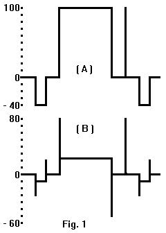 The 762 Khz sine wave is not equivalent to pre- emphasized video.
See my figure 1.B. for the video waveform at the output of the
pre-emphasis network. A test tone (sine wave) of 1.0 Vp-p at
2.333 Mhz and 1.0 Vp-p of composite video applied to the input of
the pre-emphasis network will be exactly the same amplitude at
the output of the pre-emphasis network. Note that the sync does
not contribute to the peak-to- peak amplitude at the output
assuming fast (125 nanosecond, as per CCIR 567) rise time from
pedestal to white and fall time from white to pedestal. The 1.0
Vp-p at 2.333 Mhz test tone goes through the pre-emphasis
network 140/100 IRE (2.92 db) higher than a test tone of 1.0 Vp-p
at 762 Khz.
The 762 Khz sine wave is not equivalent to pre- emphasized video.
See my figure 1.B. for the video waveform at the output of the
pre-emphasis network. A test tone (sine wave) of 1.0 Vp-p at
2.333 Mhz and 1.0 Vp-p of composite video applied to the input of
the pre-emphasis network will be exactly the same amplitude at
the output of the pre-emphasis network. Note that the sync does
not contribute to the peak-to- peak amplitude at the output
assuming fast (125 nanosecond, as per CCIR 567) rise time from
pedestal to white and fall time from white to pedestal. The 1.0
Vp-p at 2.333 Mhz test tone goes through the pre-emphasis
network 140/100 IRE (2.92 db) higher than a test tone of 1.0 Vp-p
at 762 Khz.
Since by definition the 762 Khz test tone should modulate the FM
carrier 8 Mhz p-p (4 Mhz peak) deviation, then the 2.333 Mhz test
tone -and pre-emphasized video- will modulate the FM carrier
140/100 IRE x 8 Mhz equals 11.2 Mhz p-p or 5.6 Mhz peak
deviation.
Note that this is exactly the same total deviation described
above without pre-emphasis except that in this case the sync does
not contribute to the peak-to-peak deviation. The 100 IRE (0.714
Vp-p) of video (exclusive of sync) applied at the input of the
pre-emphasis network is transformed to 140 IRE at the output.
(This 140 IRE is normalized to the level of the 2.333 Mhz test
tone at the network output or approximately 0.94 Vp-p). The
transformed video gain is 140/100 IRE or 2.92 db which is exactly
the same as the attenuation for the 762 Khz test tone through the
pre-emphasis network compared to the 2.333 Mhz test tone. The
selection of 762 Khz as the "relative 0 db level" on the
pre-emphasis curve is an attempt to correlate video (a square
wave) with the sine wave response of the network.
Pre-emphasis for FM TV is much more than a noise reduction
scheme. The pre-emphasized video has its "average picture level"
reduced by a factor of approximately 6.2. The net result is a
reduction in the asymmetrical deviation of the video and a
corresponding reduction in necessary system bandwidth at RF. The
necessary bandwidth can only be calculated for sine waves. If
the deviation is held constant at 5.6 Mhz peak, modulation
frequencies of 762 Khz, 2.333 Mhz, and 8.0 Mhz will require a
flat bandpass of approximately 16.5 Mhz, 25 Mhz, and 45 Mhz
respectively at RF. Note that for a given deviation the higher
modulating frequencies require greater bandwidth. The necessary
RF bandwidth for a complex modulating waveform such as video can
not be calculated directly.
An empirical approach is practical and in my experience an RF
carrier deviation of 5.6 Mhz peak by pre-emphasized video will
require a flat bandpass of approximately 25 Mhz at RF. Microwave
radio equipment designed to carry the video of CCIR 567-1 and FM
carrier deviation of CCIR 276-2 is usually designed for a -3 db
system bandwidth at RF of 30 Mhz to achieve a pancake flat
response of 25 Mhz centered on the carrier. Deviation can not
occur within the full -3 db, 30 Mhz bandwidth at RF because
intermodulation will occur in the non-linear portions at the
shoulders of the response curve.
The receiver IF filters are normally the narrowest bandpass in
the system and therefore set the system bandwidth. The bandwidth
of 30 Mhz will allow headroom for 5.6 Mhz peak deviation by
pre-emphasized video plus a margin of approximately 15 percent
for a maximum deviation of approximately 6.5 Mhz peak before
serious distortion occurs.
Those of you who are microwave radio technicians for video
systems are probably already familiar with the deviation
calibration procedure for CCIR Recommendation 276-2. A test tone
of 1.0 Vp-p at 2.333 Mhz is applied at the input of the
pre-emphasis network. The RF carrier is monitored and the
deviation control adjusted for a first bessel carrier null which
indicates a modulation index of 2.405. The RF carrier deviation
at the first carrier null is 2.333 Mhz x 2.405 equals 5.6 Mhz
peak deviation. Deviation is directly proportional to amplitude
at the output of the pre-emphasis network which is also the input
to the frequency modulator.
The pre-emphasized video at the output of the pre-emphasis
network is the same amplitude as the 2.333 Mhz test tone and its
deviation is also 5.6 Mhz peak. If a 1.0 Vp-p at 762 Khz test
tone is applied to the pre-emphasis network it will be 100/140
IRE times the level of the 2.333 Mhz test tone at the network
output. In other words, the deviation for the 762 Khz test tone
will be 5.6 Mhz x 100/140 equals 4.0 Mhz peak deviation as per
CCIR Recommendation 276-2 paragraph 2. requirements. The
microwave radio equipment and deviation calibration procedure
described above does not allow adequate linear deviation headroom
for the addition of any subcarriers to the video. Deviation
beyond the linear limits causes distortion in the demodulated
signal and intermodulation between the various components of
video and the subcarriers. The demodulated output of the
subcarriers will in turn contain products of intermodulation
which will seriously degrade their signal-to-noise ratio.
CCIR Recommendation 576-1 paragraph D.3 assumes no subcarriers on
the video, not even for program audio. The chrominance
subcarrier is the only one mentioned and it is considered an
integral part of the "video signal". Amateurs wishing to use
"commercial" FM TV standards incorporating subcarriers must look
to standards other than the "European" CCIR Recommendations.
Luckily these standards exist as the "North American" standards
of EIA-250-C.
"Electrical Performance of Television Transmission Systems"
EIA-250-C allows for subcarriers and in practical systems up to
four are used. Four subcarriers may seem like more than enough
but when you consider their use for program audio. intercom,
control, and metering just to mention a few, they are quickly
used up.
Microwave radio equipment designed to carry the video and
subcarriers of EIA-250-C usually has a -3 db system bandwidth of
22 Mhz in order to obtain a pancake flat bandpass of 16 Mhz
through the IF center frequency. This allows for a maximum
operating deviation of 4.0 Mhz peak plus a tolerance of 10 to 20
percent before nonlinear operation occurs. Calibration is
usually accomplished by applying a test tone of 1.0 Vp-p at 762
Khz to the input of the pre-emphasis network and adjusting the
deviation control for a first carrier null. As before, the first
carrier null indicates a modulation index of 2.405 and 2.405 x
0.762 Mhz equals 1.833 Mhz peak deviation.
The pre-emphasis network is exactly the same one used by CCIR.
The 2.333 Mhz test tone and pre-emphasized video will both be
140/100 times higher than the 762 Khz test tone at the network
output. As before, deviation is directly proportional to
amplitude at the pre-emphasis network output and 1.833 Mhz x
140/100 equals approximately 2.6 Mhz peak deviation by the
pre-emphasized video. The amplitude of each standard subcarrier
is usually 10 percent (-20 db) of the composite video amplitude
or 0.1 Vp-p. Four subcarriers of 6.2, 6.8, 7.5, and 8.2 Mhz each
will add together in-phase approximately 600,000 times each
second. Their in-phase addition will equal the sum of the
amplitudes of the individual subcarriers. 1.0 Vp-p composite
video plus four standard subcarriers will add up to 1.4 Vp-p at
the input of the pre-emphasis network. At the output, the pre-
emphasized video plus subcarriers will be approximately 1.43
times the video alone due to the placement of the subcarriers on
the pre-emphasis frequency response curve. From above, the
deviation by the video is 2.6 Mhz peak and 2.6 Mhz x 1.43 equals
approximately 3.7 Mhz peak deviation by the video plus four
subcarriers. This is just under the 4.0 Mhz peak operating
linear deviation design limit for microwave radio equipment with
a -3 db RF system bandwidth of 22 Mhz.
Some editions of the ARRL Handbook described a deviation
calibration procedure using a test tone of 0.457 Vp-p at 762 Khz
applied at the input of the pre-emphasis network and adjusting
deviation for a first carrier null. Deviation for the test tone
is 1.833 Mhz peak. Increasing the level to 1.0 Vp-p causes the
deviation to increase by a factor of 1.0 / 0.457 and 1.833 Mhz x
1.0 / 0.457 equals 4.0 Mhz peak deviation for the 762 Khz test
tone. This result is exactly the same as required for the
"European" CCIR Recommendation 276-2.
Amateur FM TV operators must be careful to use an appropriate
calibration procedure consistent with the system bandwidth of the
radio equipment used. I am quite familiar with a television
broadcasting company which bought a new microwave radio system to
use for many hundreds of miles of studio-transmitter links. This
was Lenkurt radio equipment incorporating all the research and
development of Bell Laboratories and many years experience of the
Bell Telephone system -premium microwave radio equipment with a
22 Mhz system bandwidth.
The engineer for the broadcasting company proceeded to calibrate
the system for FM TV by using the test tone of 1.0 Vp-p at 2.333
Mhz and a first carrier null. The error was then compounded by
adding four subcarriers which resulted in a total deviation of
5.6 Mhz x 1.43 equals approximately 8 Mhz peak deviation. There
was plenty of distortion and intermodulation as this system was
designed for only 4.0 Mhz peak operating deviation. The video
was noisy, distorted, and had poor resolution. Video, sync, and
chroma noise was heard in all the subcarriers. This premium
microwave radio equipment was labeled "inferior" by the engineer
and the company replaced it at considerable cost.
Amateurs using surplus IF strips with a -3 db bandwidth of 30 Mhz
can accommodate subcarriers simply by lowering the total
deviation. Pre-emphasized video deviation can be lowered to 4.0
Mhz peak (2.86 Mhz peak for the 762 Khz test tone) and the
addition of four standard subcarriers will result in 4.0 Mhz x
1.43 equals approximately 5.7 Mhz peak deviation, well within the
linear deviation limits of the 30 Mhz system bandwidth.
Calibration can be accomplished by applying a test tone of 0.64
Vp-p at 762 Khz to the input of the pre-emphasis network and
adjusting the deviation control for a first carrier null.
Lowering the video deviation from 5.6 Mhz to 4.0 Mhz peak should
not affect the signal-to-noise ratio too much assuming
substantial limiting action.
My residence in Sheridan, Wyoming is many hundreds of miles from
any technical library. In my search for expert advisors, I sent
inquiries to approximately 20 manufacturers of microwave radio
equipment. Responses numbered only about a half-dozen from
systems engineers and none claimed to be knowledgeable about FM
TV. I did have the good luck to have the chairman of the
Electronics Industries Association subcommitte for Television
Transmission Systems as one of my advisors. This gentelman
in turn was able to interview for me the elderly gentelman who
had that charmanship at the time in the 1970's when the CCIR
405 pre-emphasis network was adopted into EIA-250-C.
I had hoped that someone would come up with specific
references to Bell Laboratories research which may have
contributed to the "North American" standards. I was told that
once a recommendation became part of an industry standard that
references to the recommendations sources were dropped causing
its loss from the literary chain of documentation.
This article reflects ideas and opinions formed during many hours
of telephone conversations with my advisors and my own 17 years
experience as a technician operating FM TV microwave radio
studio-transmitter links spanning hundreds of miles. Some of
the ideas and experience presented here are in contrast to the
popular belief about FM TV. Hopefully, any controversy resulting
from this article will lead to more articles written by
knowledgeable people with a background of practical experience.
-
- Please send E-Mail to: mathison (aatt) sdf-eu.org
- .
- Last revision 2012-12-15