Calibrate Your FM TV Receiver to Measure
Video Deviation
By
J. R. Mathison, WB9OQM
This simple calibrator and an oscilloscope
will allow calibration
of an FM TV Receiver IF system to measure
video deviation
The following is the draft of my original article which was
published in Amateur Television Quarterly (ATVQ) -
Spring 1994.
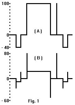 The measurement of pre-emphasized video deviation is based on the
total peak-to-peak amplitude of the pre-emphasized video compared
to the ratio of the amplitude at white. See the drawing for
comparative levels of pre-emphasized video and assume commercial
standards of 125 nanoseconds for rise and fall times to and from
white and CCIR 405 pre-emphasis.
The measurement of pre-emphasized video deviation is based on the
total peak-to-peak amplitude of the pre-emphasized video compared
to the ratio of the amplitude at white. See the drawing for
comparative levels of pre-emphasized video and assume commercial
standards of 125 nanoseconds for rise and fall times to and from
white and CCIR 405 pre-emphasis.
The low frequency white bar is attenuated by 12.92 db while the
high frequency rise and fall times are increased in amplitude by
2.92 db by the pre-emphasis network. The total difference is
15.85 db (a factor of 6.20) between total peak-to-peak amplitude
and the amplitude of white to blanking. We can measure the
composite video and infer the total pre-emphasized levels -
assuming correct pre-emphasis at the proceeding FM TV
transmitter.
The calibrator substitutes a square wave of known deviation for
the video allowing calculation of a calibration factor for the
receiver de-emphasized video output. The accuracy of the receiver
de-emphasis and video frequency response is not too important in
this case since calibration and measurement are both done at the
low frequency end of the base band range. Measurement errors
will mostly be caused by frequency response inaccuracies at the
proceeding FM TV transmitter.
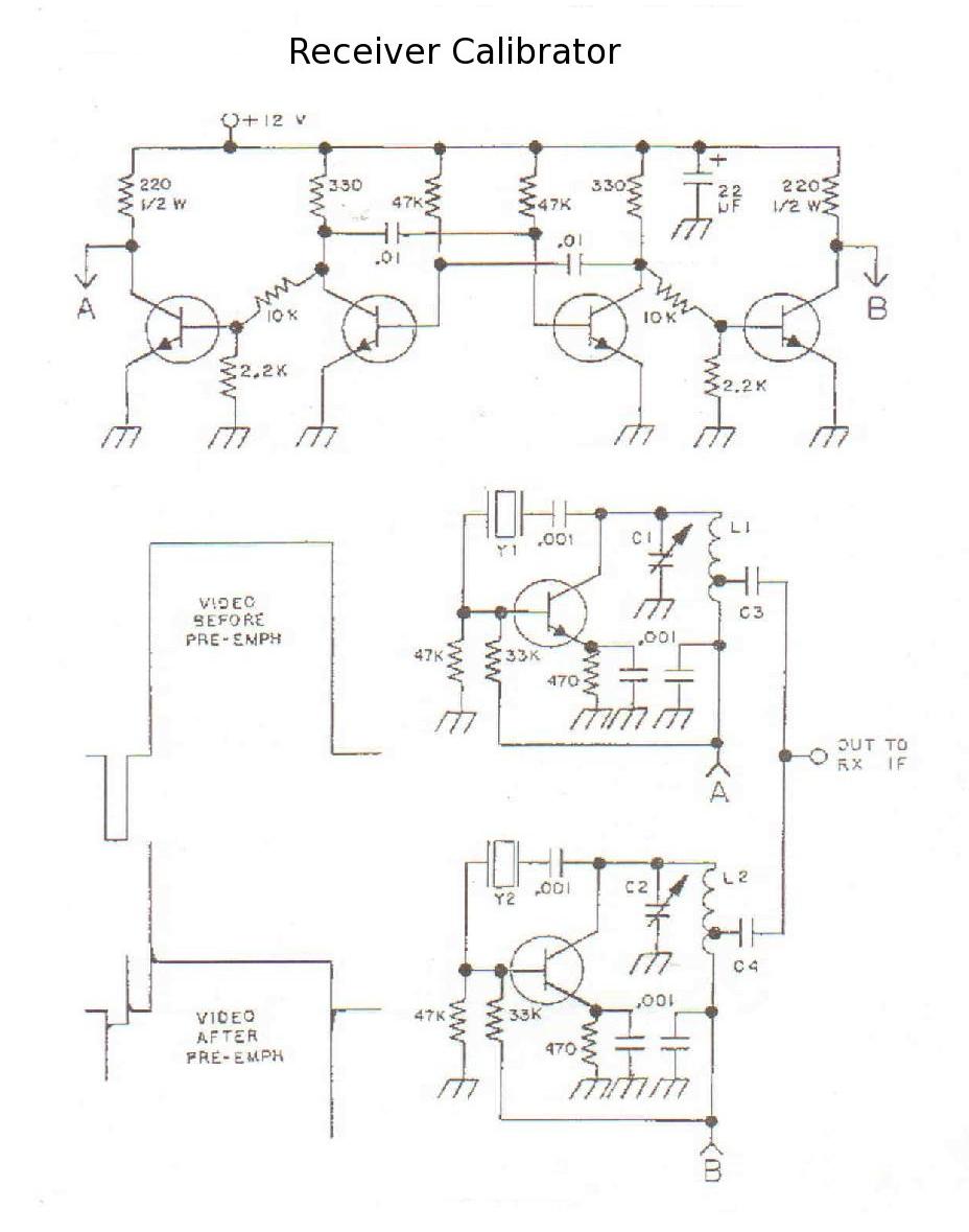
The calibrator circuit (shown at the end of this article)
consists of two crystal controlled overtone oscillators
alternately switched ON by a multi vibrator timing and switching
circuit. Crystals (surplus OK) should be chosen approximately 1
to 1.5 Mhz apart in frequency and their average frequency should
approximately correspond to your receiver IF center frequency.
The average frequency is not too critical assuming the receiver
IF has a flat RF band pass through the two switched
frequencies.
The calibrator which I use has crystals of 71.245 and 69.745 Mhz
for an average frequency of 70.495 Mhz for use with a 70 Mhz IF
system. The oscillator tank inductors (L1 & L2) are each eight
turns of number 22 enameled wire spaced one wire diameter and
formed on a 1/4 inch drill bit. Tuning capacitors (C1 & C2) are
6-50 pf trimmers which resonate at approx midrange with the above
crystals. The transistors in my unit are all 2N3904 and anything
similar should work. The oscillators use a very high level of
feedback to insure fast starting at the switching rate and a good
quality square wave at the receiver video output. Oscillator
output capacitors (C3 & C4) are identical wire gimmicks of 1 or 2
pf tapped down on the tank coils at 2 turns from the ground
end.
Calibrator adjustment is performed by feeding it's output into
the receiver IF system and using wire cutters trim the C3 & C4
wire gimmicks the same amount for correct RF level into your IF
system. Tune C1 & C2 for best square waveform as observed on an
oscilloscope connected to the receiver video output. The
calibrator switches frequencies at a rate of approximately 2860
hz which should be well above the low frequency limitations of
some video amplifiers.
Receiver calibration is done by measuring the peak-to-peak
amplitude of the square wave (ignore any overshoot) at the
receiver de-emphasized video output and calculating the
calibration factor using the formula:
Calibration Factor = (Fh - Fl) (6.2 / 2) (0.714 / sq w)
Where:
Calibration Factor = peak deviation in Mhz per volt of composite
video.
(Fh - Fl) = frequency difference between the two
calibrator crystals.
sq w = peak-to-peak amplitude of the square
wave in volts.
Operational measurements of pre-emphasized video deviation are
made by measuring the total peak-to-peak amplitude of the
composite video (sync tip to white) in volts and multiplying by
the receiver calibration factor. Some cautions are in order at
this point. The video must contain white. You may have to watch
it for a while on the oscilloscope to determine the actual white
level. Video-to sync ratio must also be correct. If not,
measure the level from blanking to white and multiply by 1.4 to
get a corrected composite video amplitude to multiply by the
calibration factor.
Subcarrier deviation may also be measured if your calibrated
de-emphasized test point carries them. Use the same calibration
factor as for composite video. The frequency response of your
de-emphasis network and video amplifiers now become important
because measurement is done at the high frequency end of base
band range but calibration was done at the low end. Filter out
one subcarrier at a time for peak-to-peak amplitude measurement
on the oscilloscope and correct this level by the filter
attenuation factor before multiplying by the receiver deviation
calibration factor. Subcarrier deviations will actually be a
few percent higher than indicated due to their placement of the
pre-emphasis curve.
The calibration of a FM TV receiver to measure deviation of video
which has not been pre-emphasized and the calibration of a video
test point ahead of the de-emphasis network are both the same
procedure. The calibrator (Fh - Fl) gives a reference
peak-to-peak deviation level and the receiver peak-to-peak
calibration factor is obtained by direct proportion. Divide the
peak-to-peak factor by 2 to get the peak deviation receiver
calibration factor. This simple calibrator is a lot easier to
use than setting up all the necessary test equipment to do a
Bessel carrier null calibration on your FM TV receiver. I hope
everyone finds it as useful as I have.
-
- Please send E-Mail to: mathison (aatt) sdf-eu.org
- .
- Last revision 2012-12-15